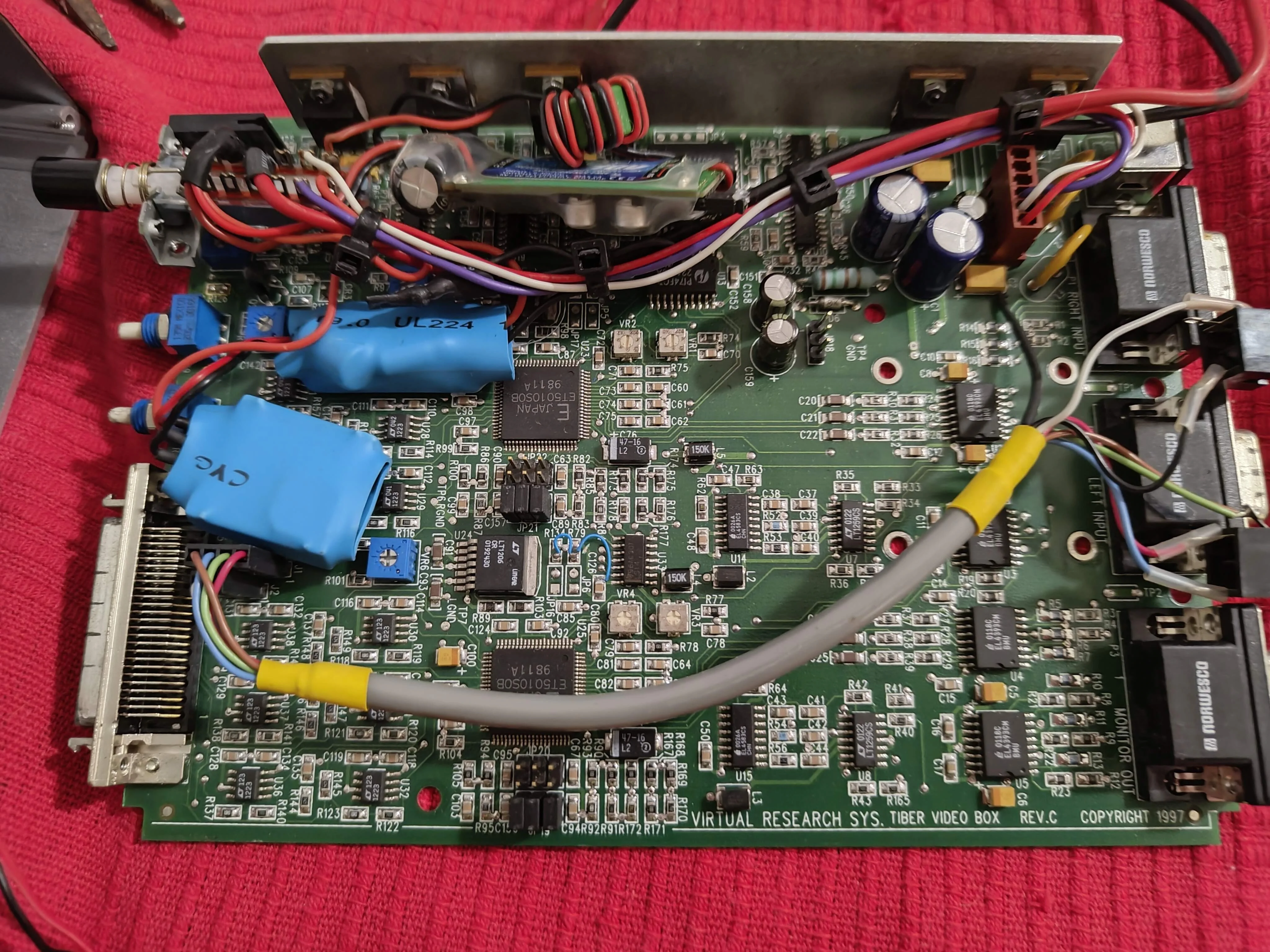
The PCB of unit M's control box
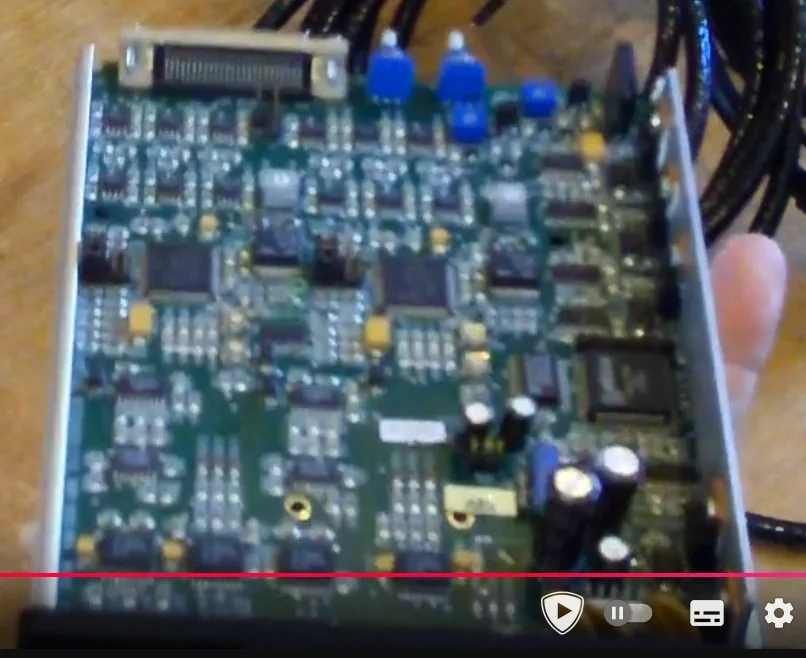
The PCB of unit T's control box
Before we start with this story, I have to introduce to you the objects and people "involved" in this thing:
I think we should also give "names" to the various units, to reference them easily. Mine has been modified, so we can call it Mod unit, or for short unit M. Kevin's doesn't have anything special so let's call it Kevin unit (unit K). VRtifact's should be the teardown unit (unit T).
What do you think about the css theme? It's inspired by Virtual Research's but inverted main colors.
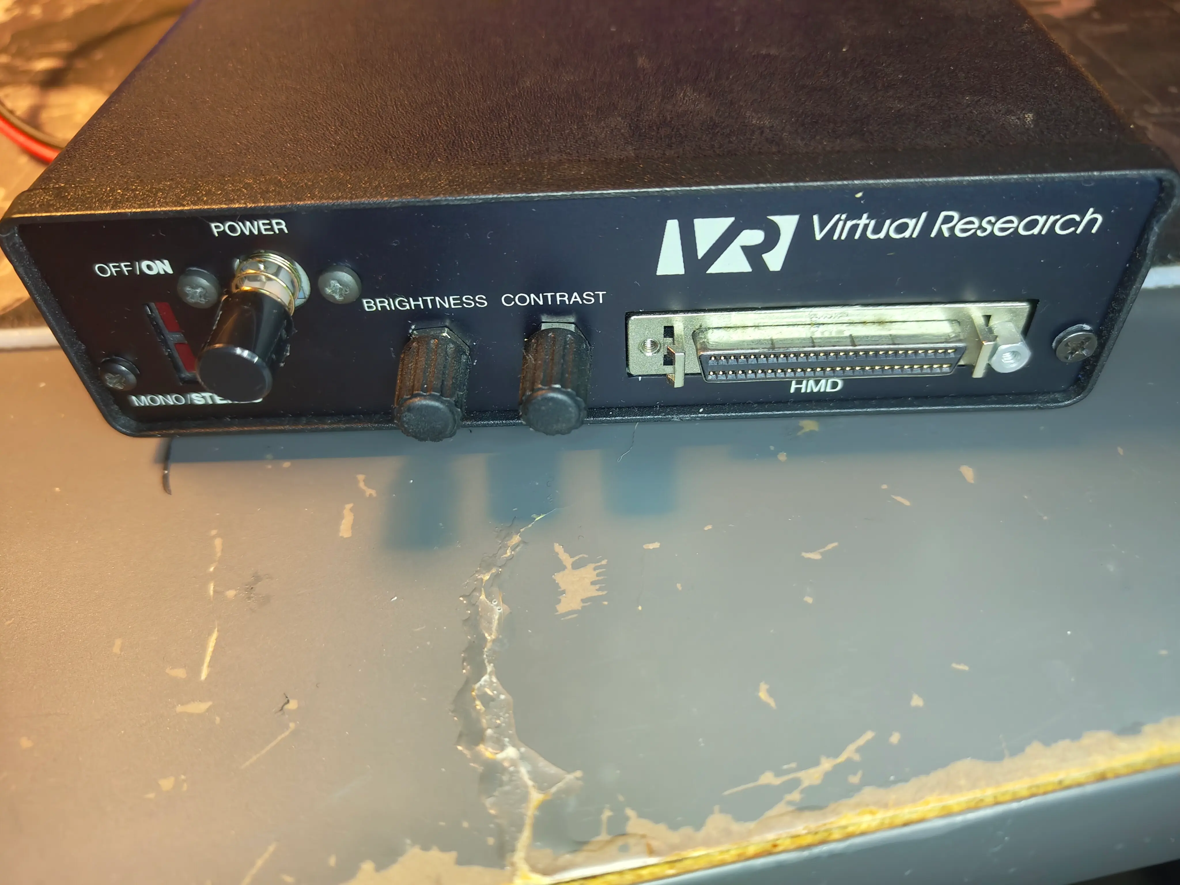
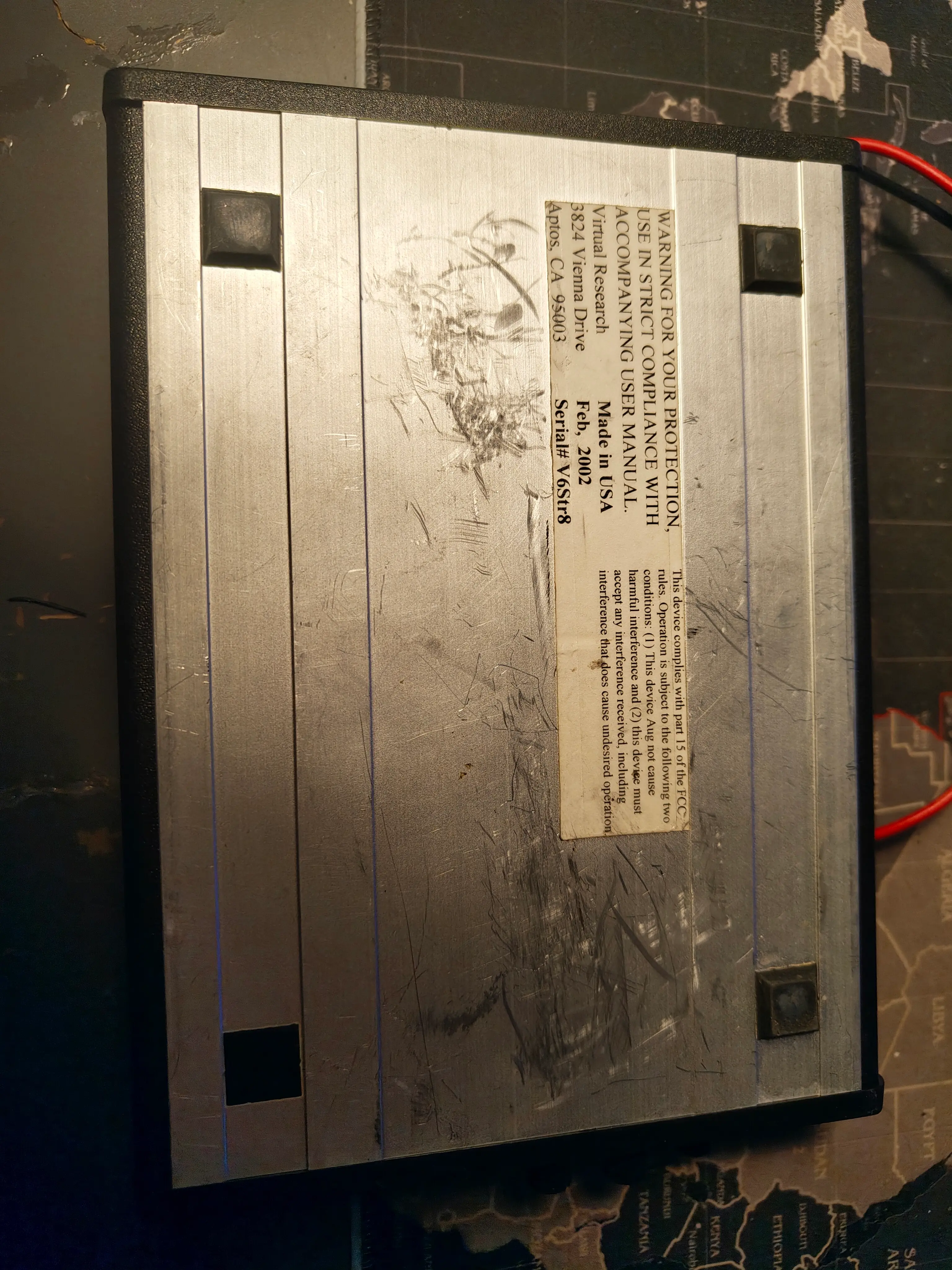
Unit M was initially produced in 2002 according to the label on the control box. While in the hands of Owner S, the control box was subjected to multiple modifications, which I spotted by comparing it to unit T. Notably, M has 2 24v (according to Wallapop guy) positive and negative wires dangling out of it, near the power connector, and a plastic wrapped pcb, all shown below.
The PCB of unit M's control box
The PCB of unit T's control box
Through Wallapop, I was able to ask a few questions to Wallapop guy:
Q: [...] Initially I hadn't noticed the 2 wires coming out of the module, were they used by you? Is the headset functioning? Also, how were they hooked up to electricity? At what amperage?
A: It was property of a store at a mall where my brother worked, the store closed and he received everything minus the charger. It works with its charger. I put 24v at 1.5a to check if the module turned on. But for it to operate correctly it requires the original charger
Q: Do the screens also turn on?
A: The screens turn on with the charger
Q: Were the 2 24v cables already there? When you got it.
A: Yes, my brother gave it to me just like that. It worked with a decoder or a device that input images in each lense. I started investigating and I found out that it can be made to work with a pc with a graphics card. But I don't have a pc like that. He told me that each set of headset and module costed 6000 euro
At the time, this was fairly useful. But it still doesn't answer why the 2 wires are present. Were they a fix for a partially broken power adapter? Or an attempt at making the headset work without the original power adapter?
The seller used 24v with 1.5a and has stated he researched the headset. As expected, if we check on the manual, we see these voltages: +5V - 3A, +24V - 0.7A, -12V - 0.5A, that add up to 37.8W, and the seller's adds up to 36W.
I'm no electrical engineer, so I think all I can do is...
Here's a few interesting images of the outside of unit M's control box, with the odd wires and the missing screws visible

Now, let us dive into the control box
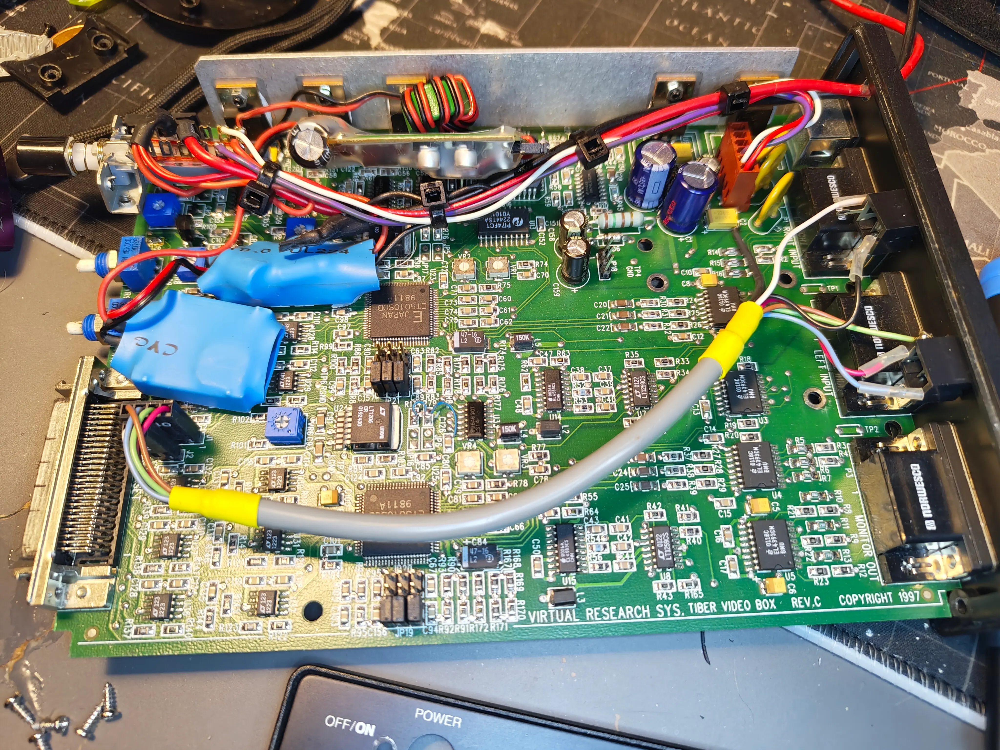
Here's an overview of the board
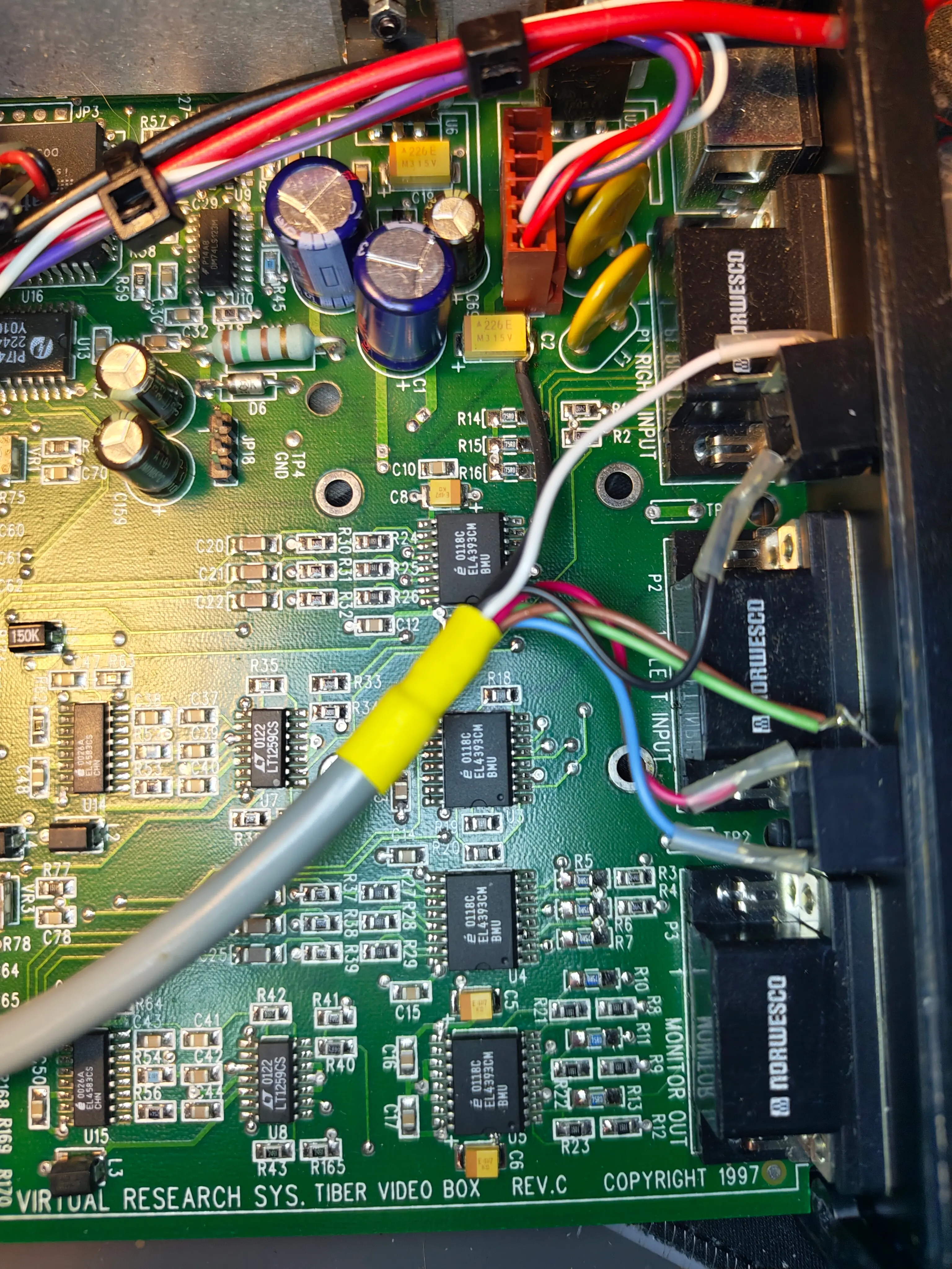
Right side hd
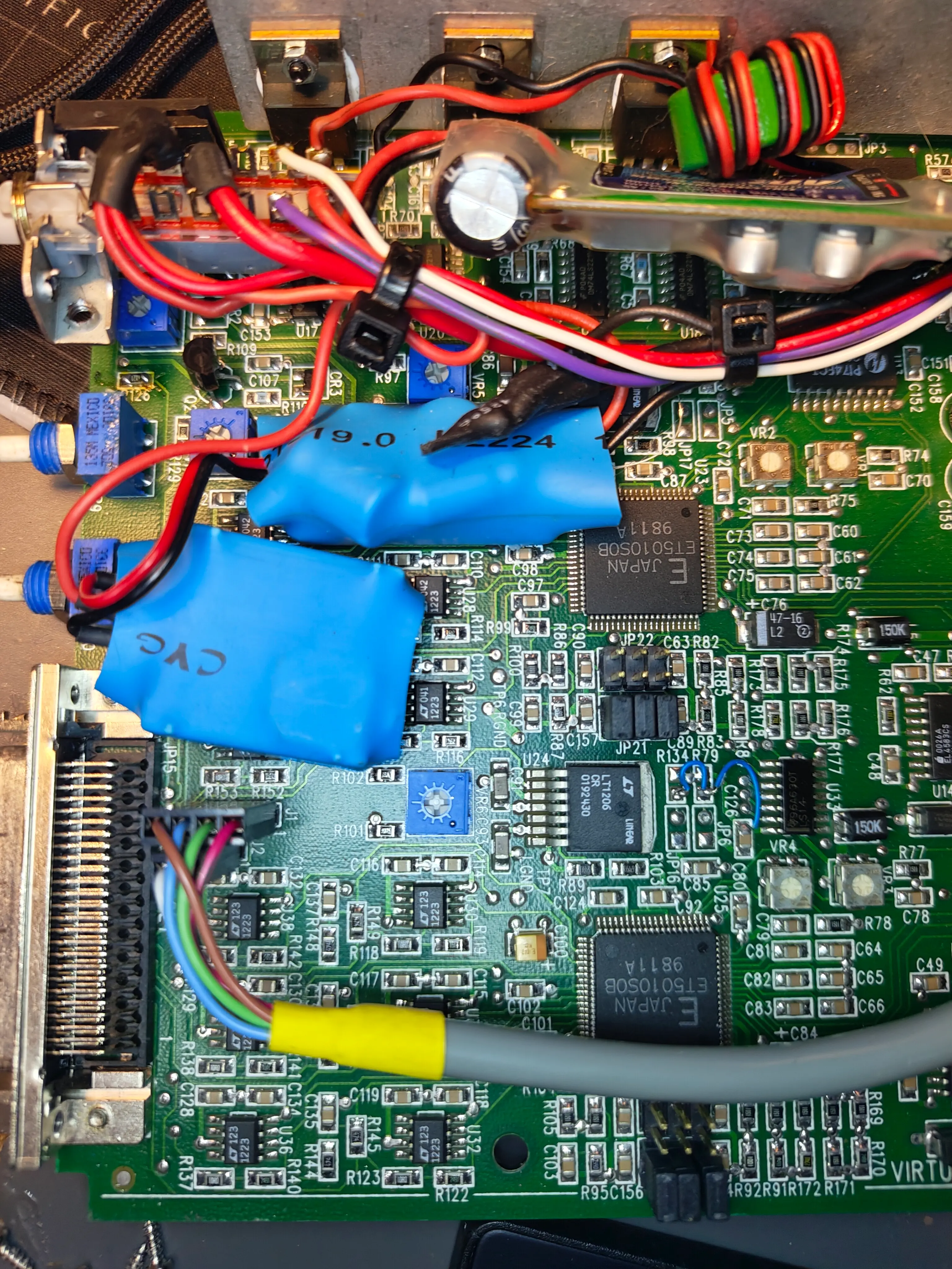
Left side hd
The fan connector for teardown reference. I am not sure if its the right way in as I didnt document it the first time but I tried to guess based on traces
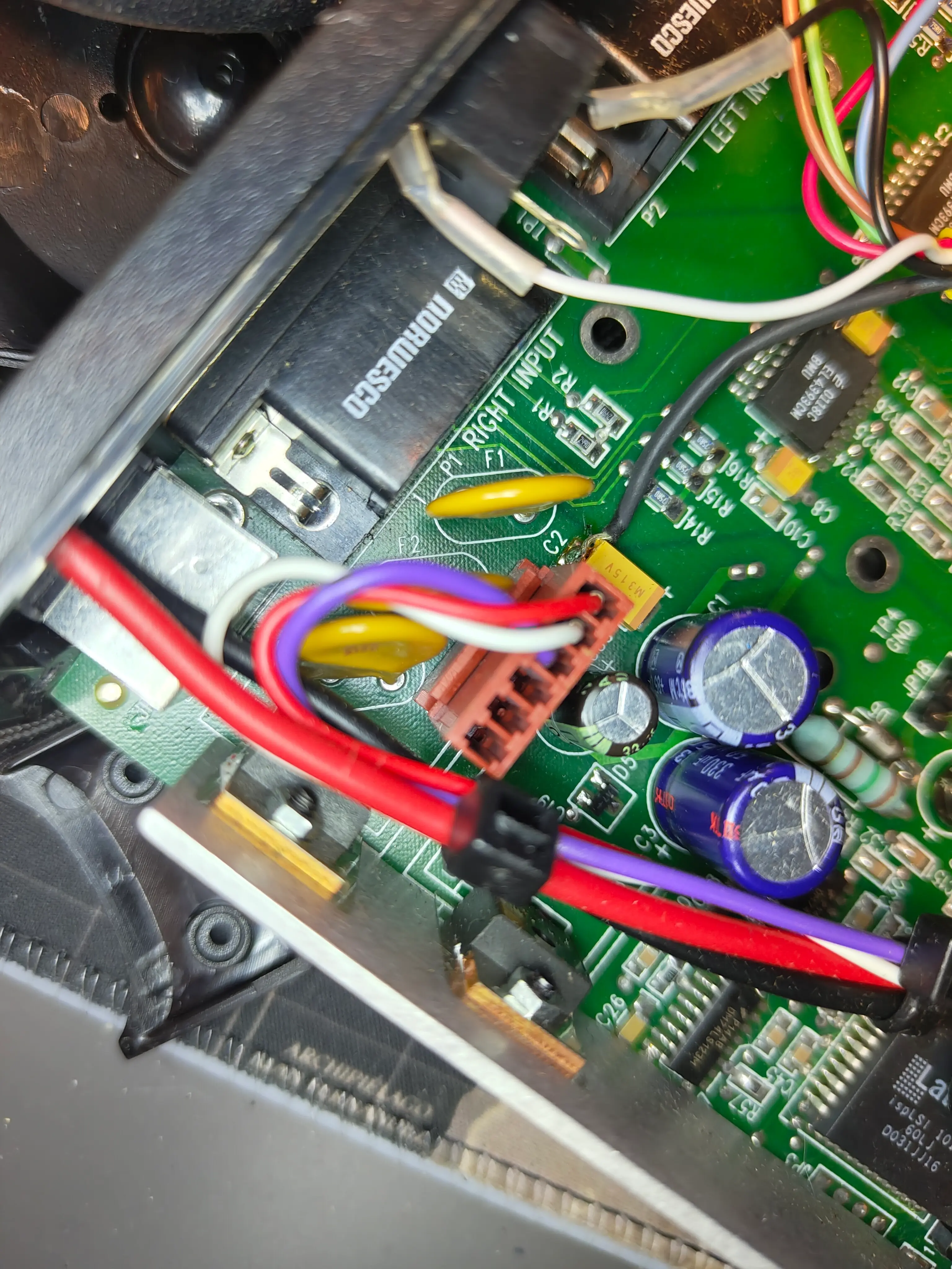
A, possibly interesting, orange connector on the side of the inputs
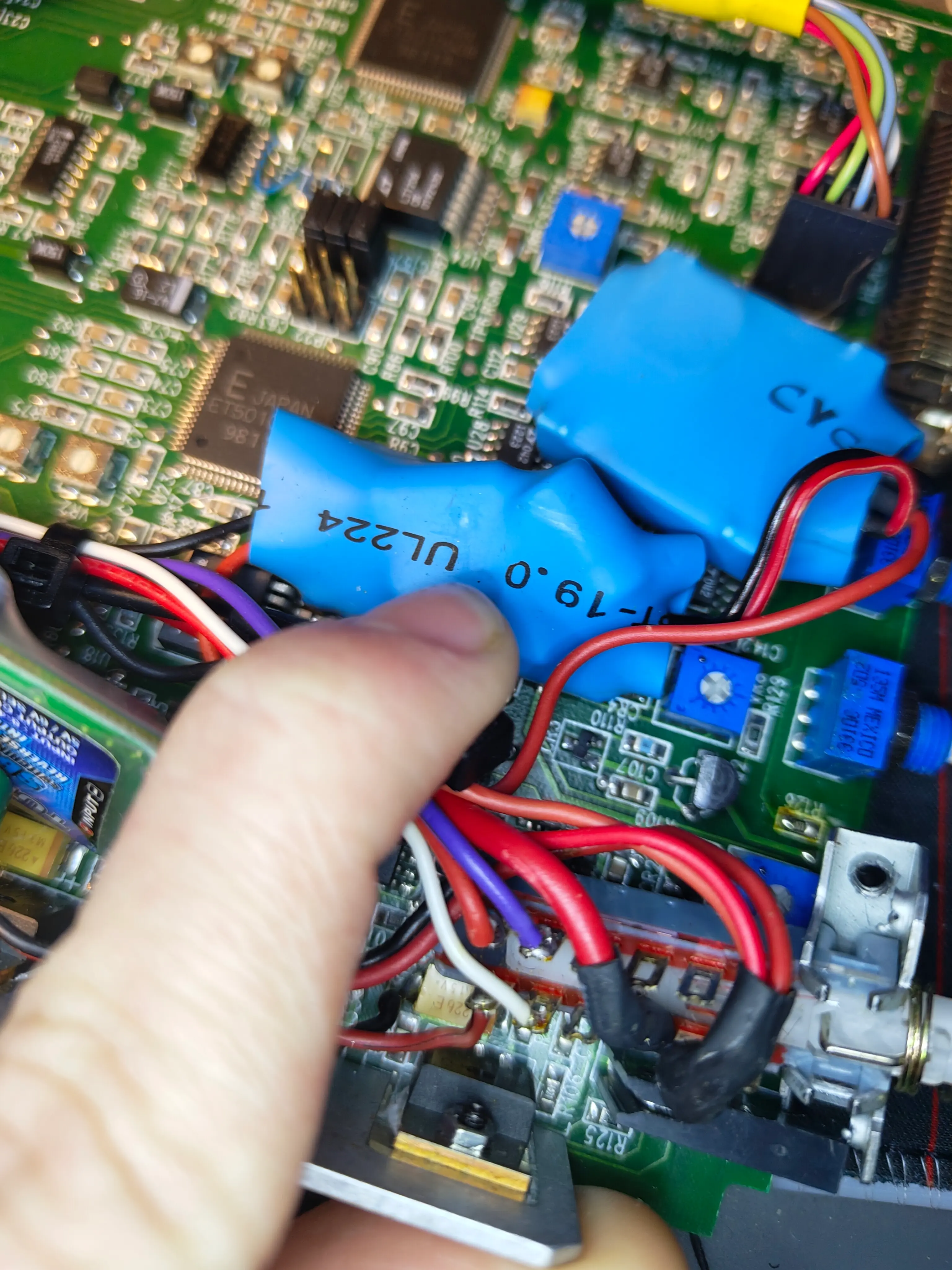
Components wrapped with blue rubber
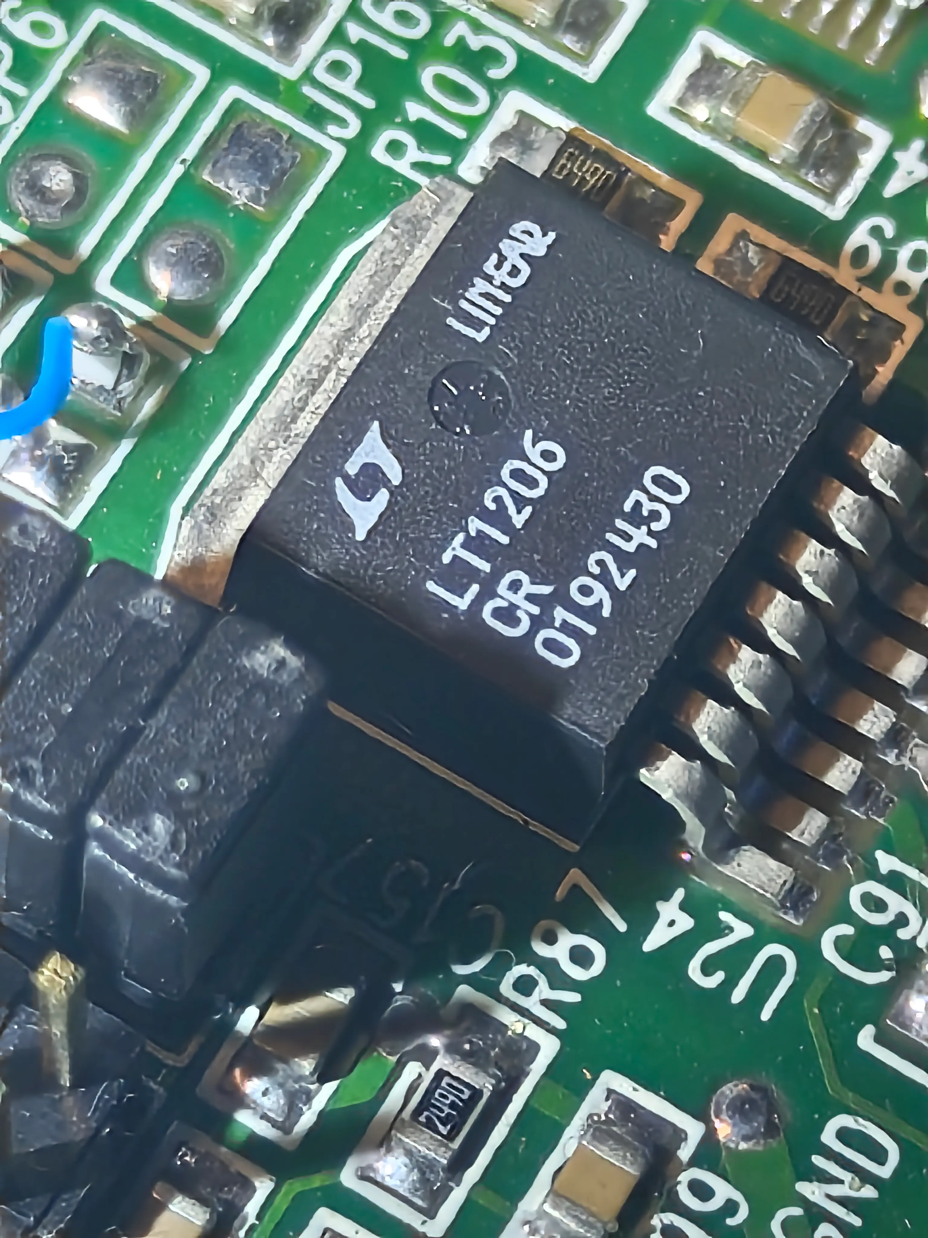
Logo found on many ICs on the board
Logo found on many ICs on the board
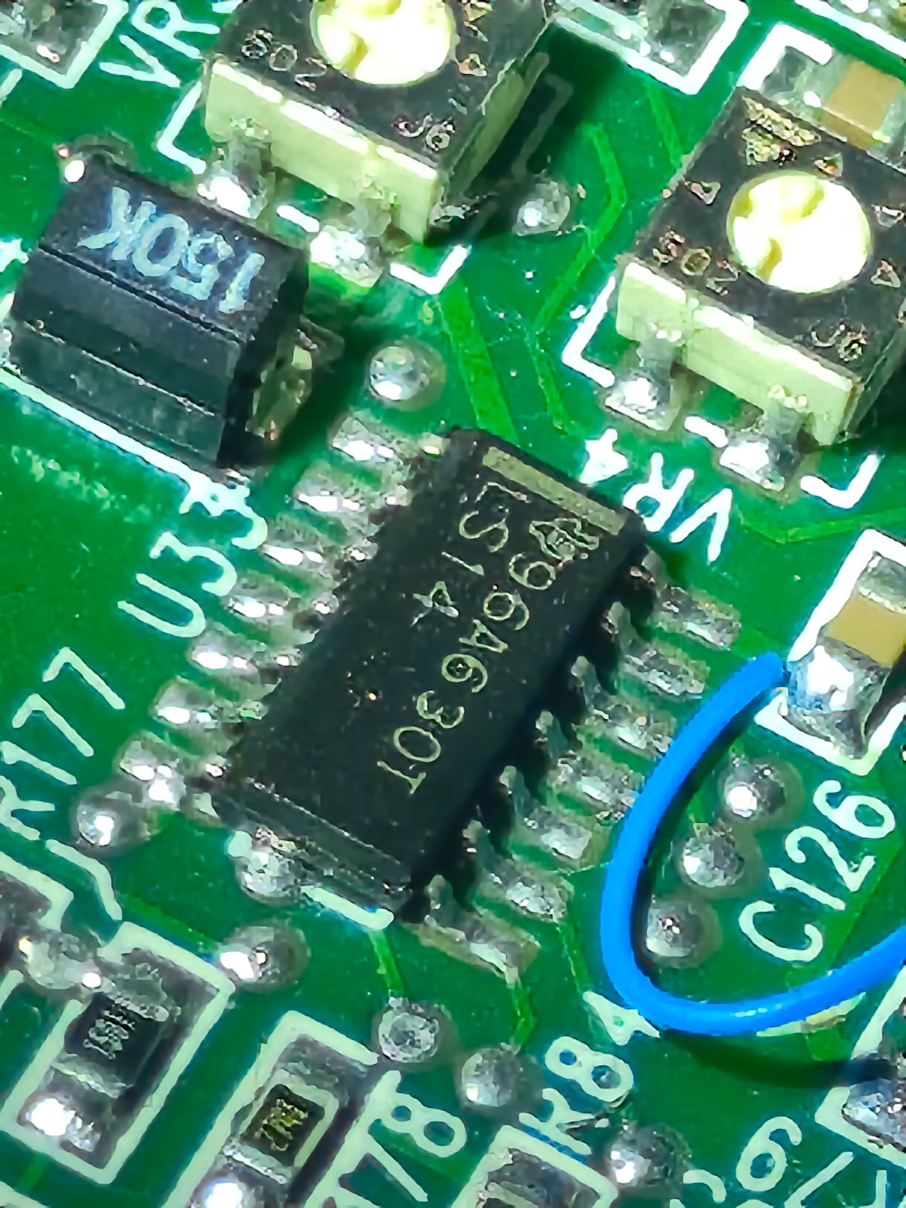
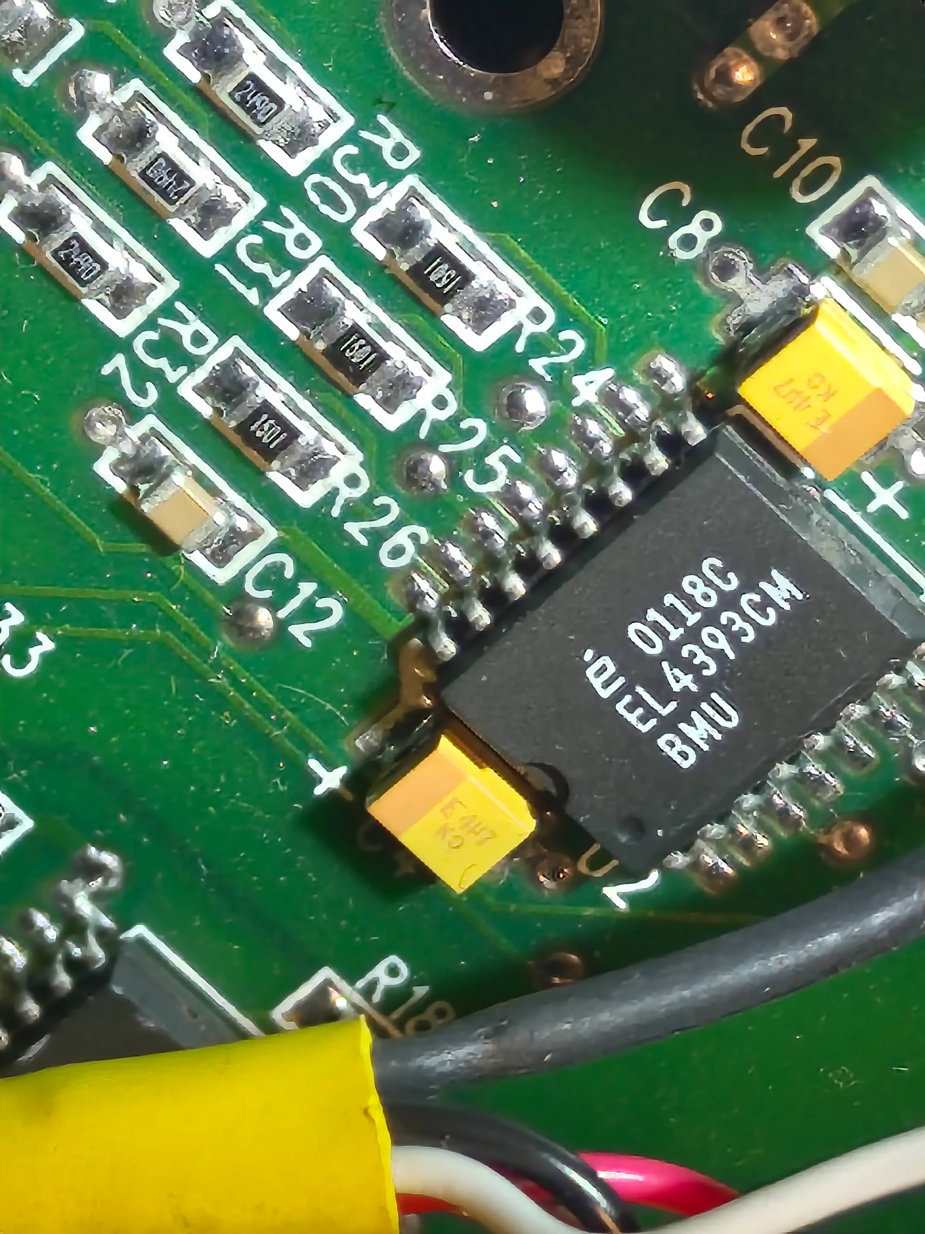
A odd looking logo, probably Texas Instruments that appears on a single IC

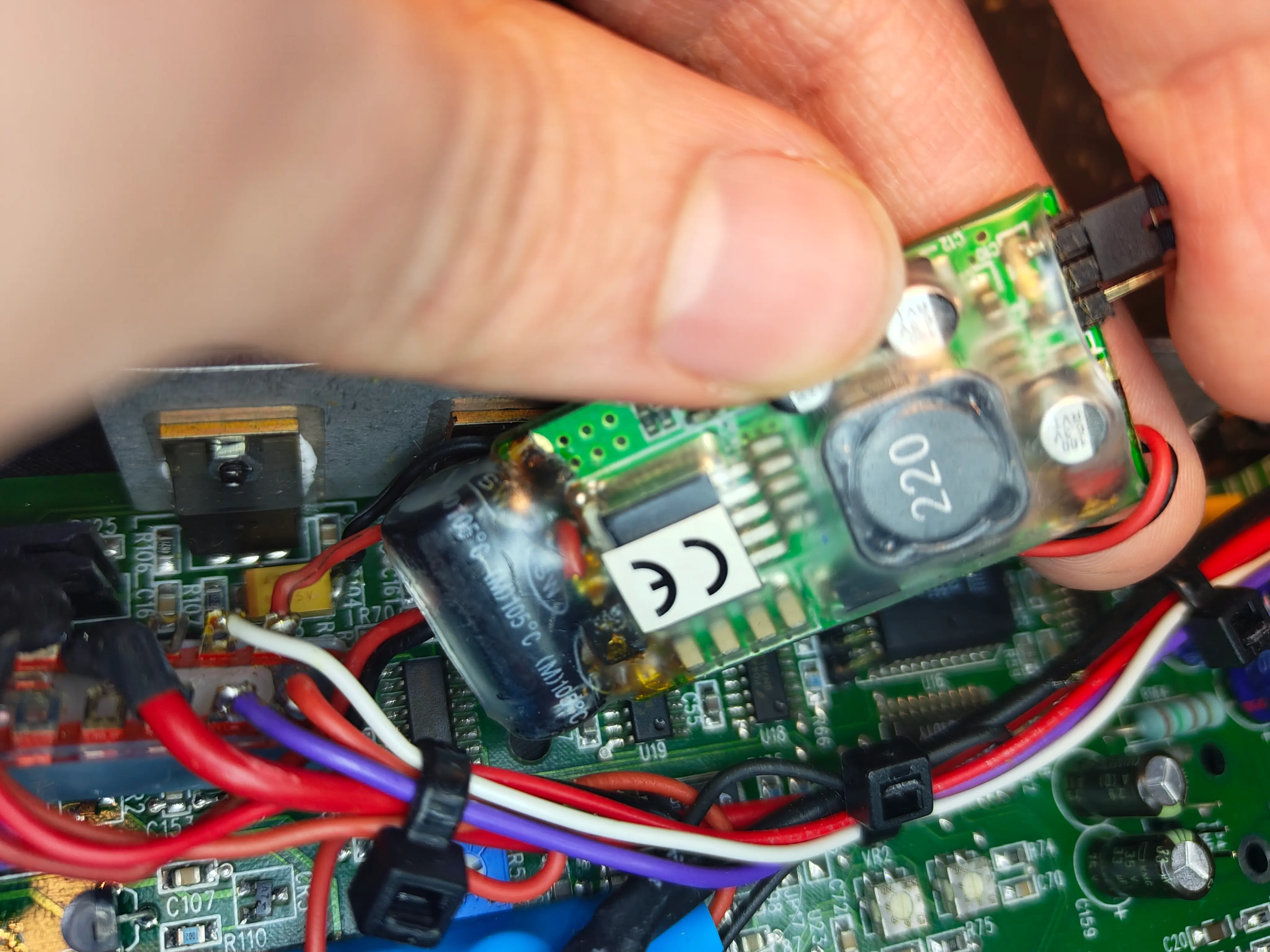
This is the aforementioned mysterious pcb wrapped in plastic. It's very interesting. Text trascribed in picture alt text
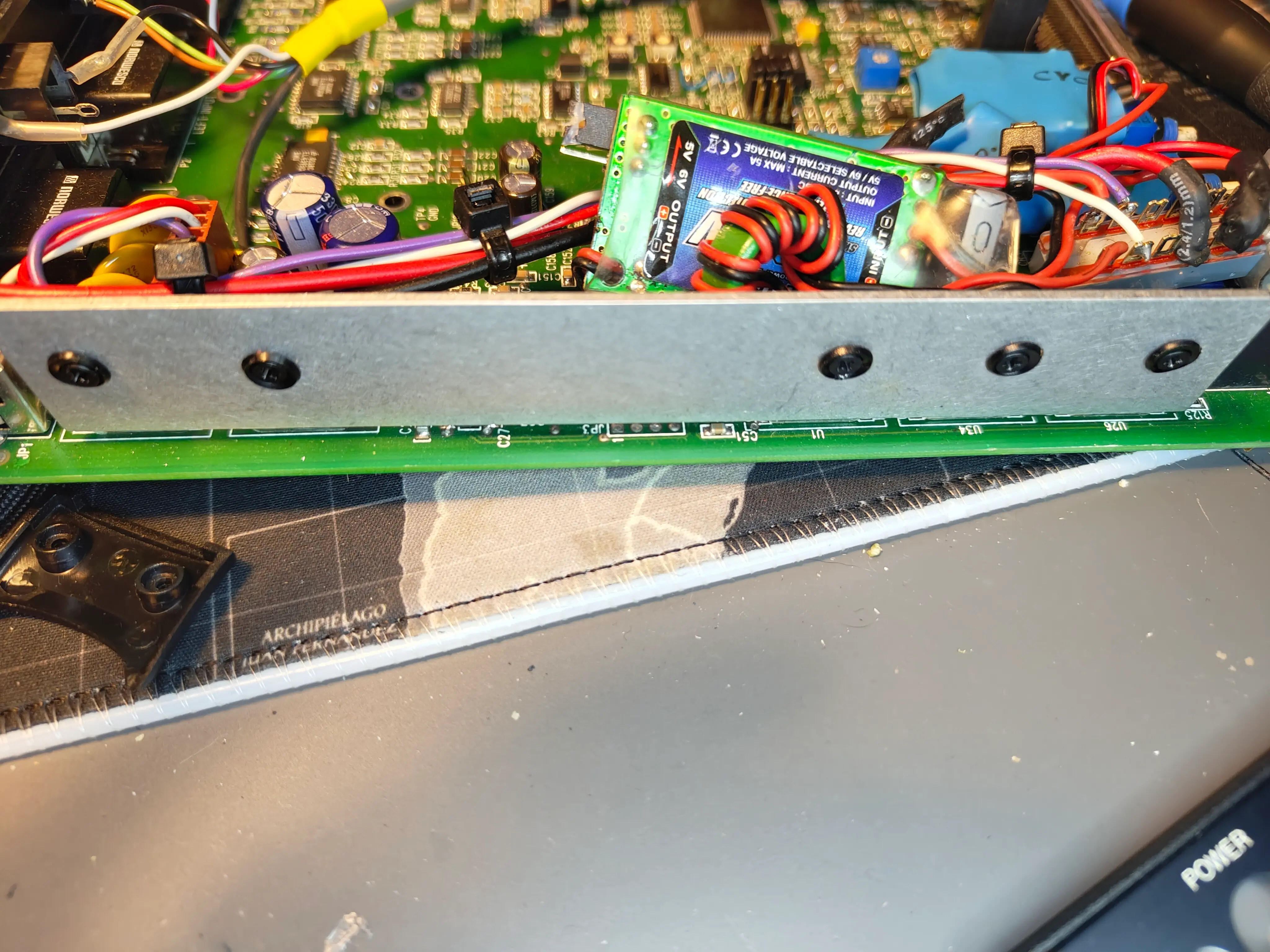
Bottom of the converter, with the european CE logo
Left side of the board, could be for grounding? I don't know enough about circuits heatsink for voltage regulators[Update]
I cannot make many assumptions, but we can note that the converter takes 8-40 volts, a range that includes 24V of the odd cables, and outputs 5V, one of the voltages mentioned in the manual. If both it and the pure 24V are hooked up properly that would leave the -12V. Looking at the whole board we can also note it has wiring for headphones and microphone, but I dont see any mic on my headset. Both the control box and the headset look very used. Now a few questions still remain unanswered: Why does the headset not work with the odd wires? Who put them there? Virtual Research themselves or Owner S?
I will add any updates here with a DD/MM/YYYY date. For any questions, tips and/or observations you can contact me on discord at the username everythingonarm
Small correction, on the side of the board there's a heatsink, thanks to zcubed.
Also, a while ago I contacted Total Power, but I omitted the interaction here as I believed it to be useless. However, for completeness sake, I decided to add it here. When looking through my emails I spotted a fairly significant one I didn't read a the time, so I've decided to transcribe the conversation here.
[ME]: Missing text, an inquiry about the HES40-32
[Total Power Rep]: Hello [ME]
HES40-32
This model is obsolete without replacement. I do not have an alternative. You might be able to find something similar at Digikey, Mouser or Allied Electronics
Best regards,
[Total Power Rep]
Total Power International, Inc.
[ME]: Thank you for the answe[r], the main issue with sourcing, or building a replacement, is the lack of a connector pinout. Is that available?
[Total Power Rep]: Hello [ME],
The connector is not available. I suggest finding an electrical equivalent and then switching the cables. When opened up, you can typically identify the outputs by the markings on the PCB. The label on the HES40 should also call out the pin voltages.
Best regards,
[Total Power Rep]
Total Power Int'l
Looking back to the VRtifacts' teardown video, we can see, as the representative said, the PSU's label has all of the voltages, but we alr knew these from the manual, and not much other info.
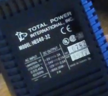
Sadly, looking up this PSU returns 0 results so I don't expect one of them to show up soon, but if it it does im happy to document the pinout.